
Dental-chair light compatibility: four interfaces to confirm before installation
Capture supply, mechanical fit, cable routing and control behaviour in one interface record, with explicit stop conditions for an unconfirmed installation.
Start with the answer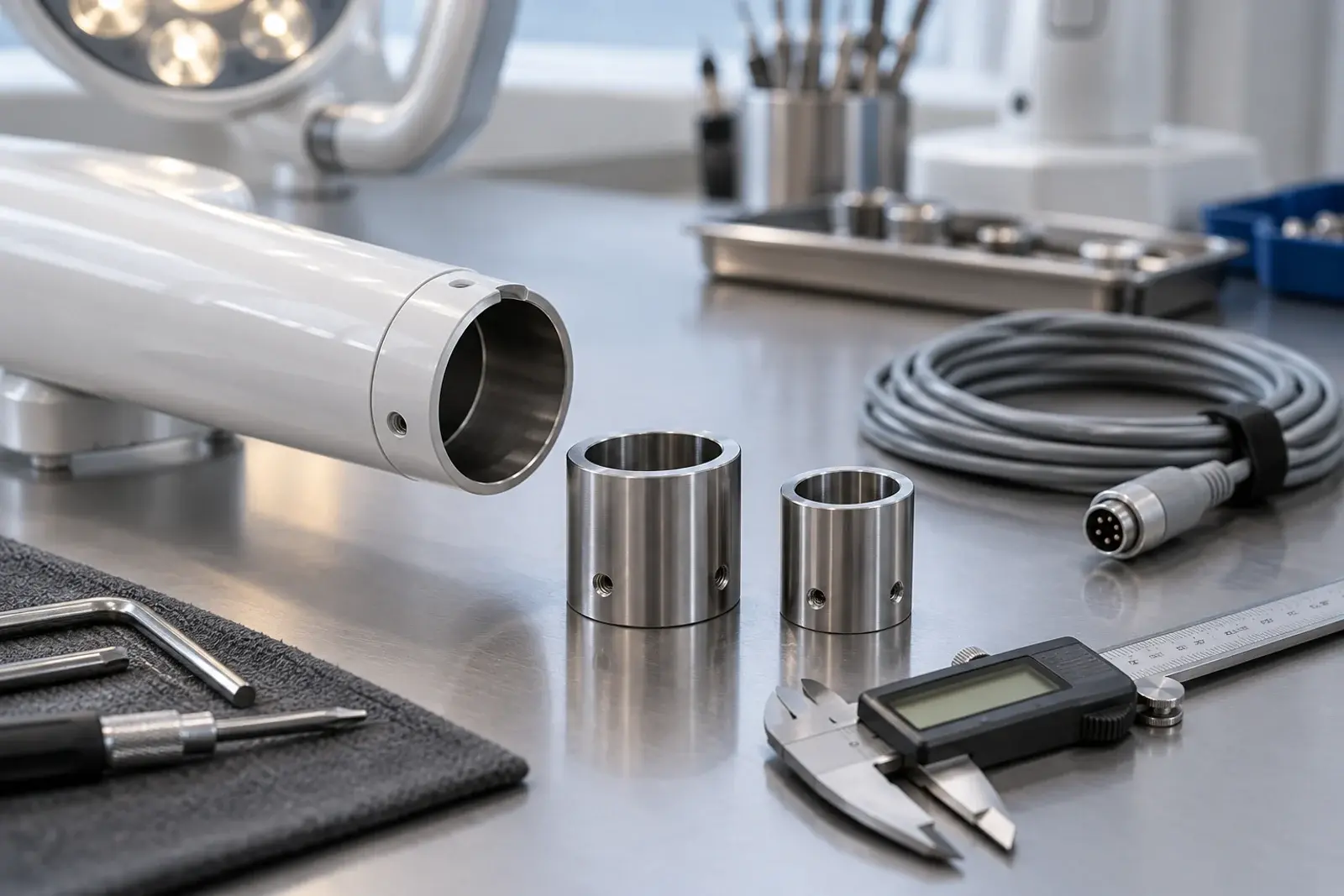
The buying decision, clearly stated.
Confirm four interfaces together: electrical supply, mechanical engagement, cable routing and operator controls. Colight's eight standard head records specify 12–24 V AC and 22 mm or 26 mm connector options; these are not an AC/DC rating or a universal-fit promise. The responsible engineer must approve the complete delivered assembly using applicable instructions and drawings.
- A matching nominal diameter does not establish engagement length, retention or load capacity.
- A lamp-head voltage range does not specify the entire chair or power-supply system.
- Stop when supply type, drawings, retention or installation responsibility remains unresolved.
Electrical supply: verify the actual source, not just a voltage label
Start with the installed chair model and the proposed lamp configuration. Obtain the applicable power-source documentation and ask the responsible engineer to confirm waveform, voltage range, capacity, protection, connection arrangement and the boundary of the lamp supply. A project record should distinguish what the chair provides from what the lamp head requires.
The verified Colight source specifies 12–24 V AC for the standard heads. Do not change that into AC/DC in a distributor spreadsheet or translate it as a universal low-voltage input. Other manufacturers may specify different electrical systems for their products; Dentsply Sirona's LEDview Plus documentation is one example. That difference is a reason to check, not evidence that the lamps are electrically interchangeable.
Evidence context: Dentsply Sirona
Mechanical engagement: the diameter is only one field
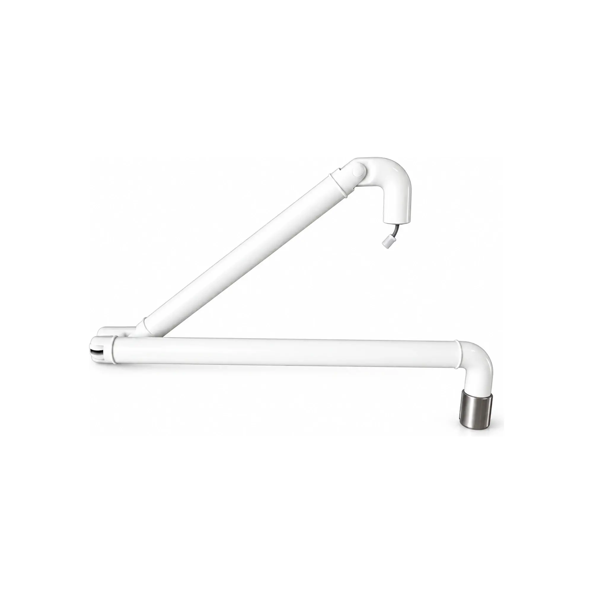
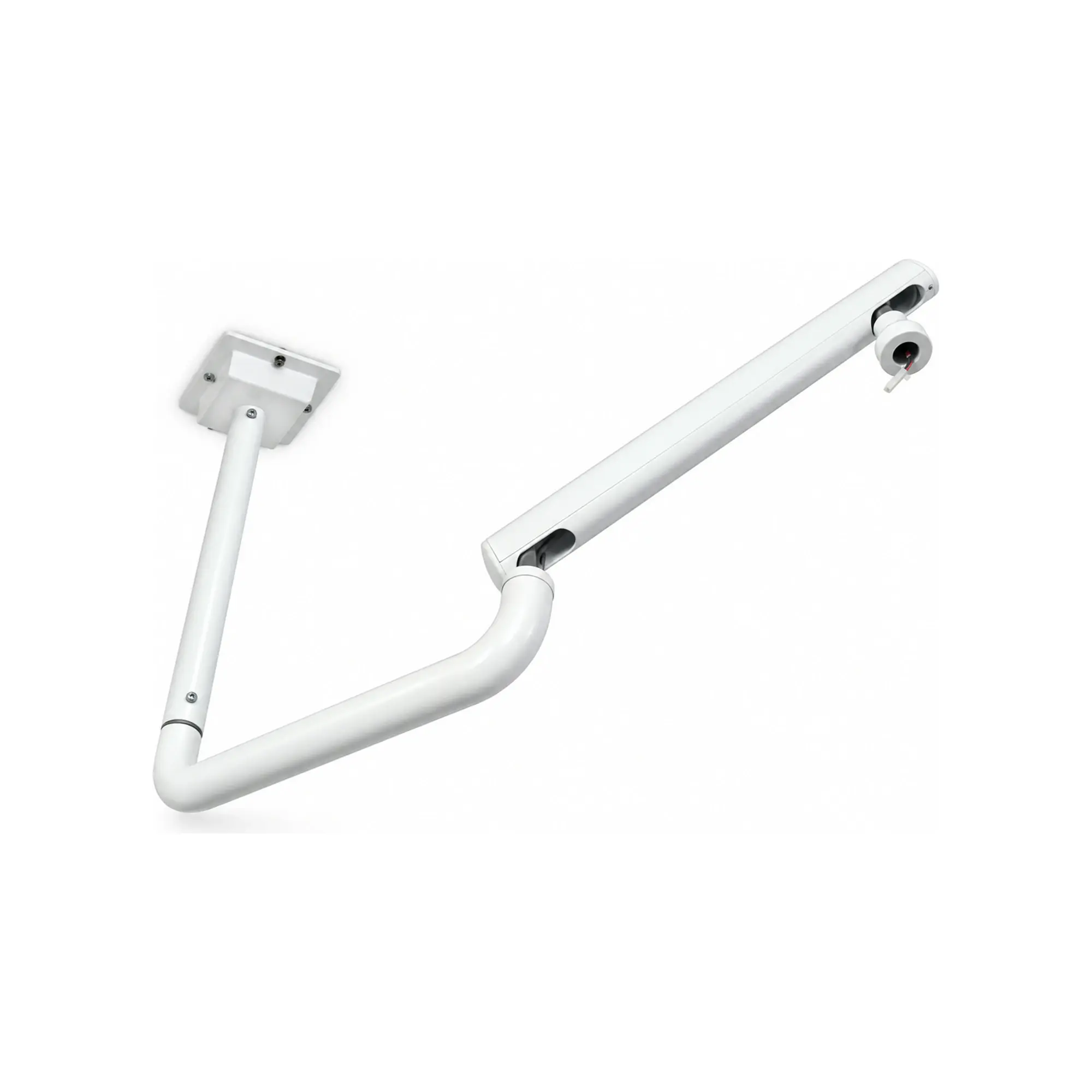
Record the mating geometry, engagement length, retention method, cable exit, allowable movement and the relevant drawing revisions. The arm and head are a coupled assembly: head mass, leverage, joint adjustment and the intended operating positions can affect whether it can be used as planned. Do not specify a load capacity that the supplier has not provided.
A 22 mm or 26 mm option is a nominal connector choice in the head catalogue. It does not establish that a collar, sleeve or improvised adapter will make an unknown arm suitable. Ask for controlled drawings and a confirmed mating arrangement. A photograph can help identify the installed equipment, but it cannot replace dimensional or engineering approval.
Cable routing and controls need separate acceptance questions
Cable routing should be reviewed through the intended movement envelope using the applicable assembly instructions. Identify exit locations, available path, connector access and the means of avoiding strain, pinching or interference. Keep this as a documented engineering review; this article intentionally provides no live-wiring sequence, pin assignment or instructions for modifying an installed chair.
Control compatibility is another interface. A head-mounted sensor or button does not establish interoperability with the chair's user interface, foot control or software. Planmeca's integrated light and camera workflow illustrates how product-specific these connections can be. Ask exactly which controls will operate the supplied lamp and which chair features, if any, have been confirmed.
Evidence context: Planmeca
Approve the assembly and control later changes
Use a signed interface record to connect the lamp model, ordered option, chair platform, mounting hardware, cable configuration and instructions. Define who installs the assembly, who checks the result and what evidence releases the installation for its intended use. An unconfirmed item should be visible as a hold, not buried in an email chain.
Once a sample is accepted, changes to the head, connector, cable or arm need a documented impact review. The fact that the replacement part looks similar does not show that prior acceptance still applies. Review the affected interface, update the configuration record and repeat relevant checks before releasing the revised combination. This is particularly important when a distributor supports several chair platforms under similar sales descriptions.
Nominal match versus a confirmed installation
This distinction is useful when a replacement enquiry arrives with only a photograph and a tube diameter.
Nominal match
- Useful for
- Helps identify a candidate connector or head family quickly.
- Check carefully
- Leaves power type, retention, load, cable path and controls unresolved.
- Decision context
- An initial enquiry and a request for the missing installation details.
Approved complete assembly
- Useful for
- Links the actual components, drawings, instructions and acceptance responsibility.
- Check carefully
- Approval applies to that configuration and platform, not every visually similar chair.
- Decision context
- A controlled OEM release or professionally assessed replacement installation.
Put the evidence beside the decision.
| Interface | Record before approval | Hold condition |
|---|---|---|
| Electrical | Confirmed source type, range, capacity and applicable instructions | AC/DC type or power-source responsibility unknown |
| Mechanical | Mating drawing, engagement, retention, load and movement scope | Only nominal diameter or photographs available |
| Cable | Exit, route, access and movement review | Strain, interference or connection details unresolved |
| Controls | Actual sensor, button or confirmed chair-control arrangement | Chair integration assumed from another product |
| Configuration release | Sample identifier, revisions and responsible approvals | Delivered assembly differs from the approved record |
Compatibility review with clear stop points
- 01
Identify both sides
Record the chair platform and exact proposed lamp configuration.
- 02
Collect evidence
Obtain supply information, mating drawings and applicable instructions.
- 03
Review interfaces
Have the responsible technical parties resolve each of the four interfaces.
- 04
Assess the assembly
Evaluate the actual mounted configuration and intended movement.
- 05
Release or hold
Approve the documented combination or retain a visible unresolved hold.
Worked example: the right diameter with the wrong assumptions
A hypothetical installer is offered a replacement head because the old and new tube labels show the same nominal diameter. Before accepting the replacement, the installer requests the chair supply information, engagement drawing, retention arrangement and arm loading information. The existing photograph alone answers none of those questions completely.
If the supplier cannot yet confirm the supply type or a retention detail, the job remains on hold. It is not resolved by calling the product low voltage or by adding an unapproved sleeve. Once responsible parties confirm the combination and installation instructions, the assembled configuration can be assessed and recorded. This example describes a purchasing and engineering handover; it is not a method for adapting or energizing an unknown electrical system.
Questions buyers ask next.
Does a 22 mm connector fit every 22 mm chair arm?
No. Nominal diameter is only one field. Confirm engagement, retention, load, cable exit, tolerances and movement using applicable drawings and instructions for both sides of the interface.
Can I connect a standard Colight head to a DC supply?
The verified head source states 12–24 V AC and does not establish DC compatibility. Ask the responsible engineer and supplier to confirm the proposed configuration; do not substitute the waveform based on this article.
Will the head automatically work with my chair foot control?
Not necessarily. A lamp's own sensor or button does not establish electrical or software compatibility with the chair controls. Specify the intended control arrangement and request confirmation for that platform.
What should I send with a replacement enquiry?
Send the chair identity, current head and arm photographs, known supply documentation, mating dimensions or drawings, connector and cable details, required controls and destination. Identify the installer responsible for confirming the complete assembly.
Follow the evidence.
Manufacturer and institutional sources inform the context. Colight specifications come from the verified site catalogue; competitor values are not presented as Colight test results. References were checked on 2026-10-27.
- LEDview Plus — manufacturer brochure
Industry example of model-specific electrical and composite-mode documentation. Checked October 27, 2026.
- Planmeca Solanna Vision — operating light and camera integration
Industry reference for integrated camera and dental-unit workflows; these features are not attributed to Colight. Checked October 27, 2026.
Corrections or missing project evidence: contact Colight. The page supports purchasing discussions and does not provide patient-specific care, electrical installation instructions or a legal market-access decision.